Acoustic Characteristics of Phase-Synchronized Adjacent Propellers
 ✉
Djamel Rezgui
Mahdi Azarpeyvand
✉
Djamel Rezgui
Mahdi Azarpeyvand
Affiliation : Department of Aerospace Engineering, University of Bristol, Bristol BS8 1TR, United Kingdom.
✉ en22804@bristol.ac.uk
Introduction
In recent years, urban air mobility has emerged as a promising solution to the challenges of modern transportation. By using small aircraft to move people and goods within cities, it aims to reduce traffic congestion, cut down on pollution, and provide more sustainable travel options [1,2]. The rapid growth of interest in this field has also driven significant improvements in rotor and aircraft design. However, one of the biggest hurdles facing urban air mobility is the issue of noise. The loud sound created by aircraft rotors can impact communities, making noise control an essential factor in gaining public acceptance and successful integration into existing transport systems.
One approach gaining attention in this field is Distributed Electric Propulsion (DEP), where multiple small, electrically powered propellers are mounted along the wing of an aircraft. This configuration offers efficiency benefits but also introduces complex aerodynamic interactions between the propellers and the wing [3]. These interactions can change the way air flows, influence propeller performance, and create additional noise challenges. Researchers are working to better understand how these factors combine, since propeller noise remains a significant barrier to wider adoption of DEP technology in urban air mobility [4].
To address these issues, recent research has explored innovative noise reduction strategies for DEP systems. One promising method is electronically synchronizing the propellers, so that their movements are carefully coordinated. This technique, especially when applied to forward flight conditions, has the potential to reduce noise by adjusting the relative timing, or “phase,” of the propellers [5].
This experimental campaign focuses on the effect of blade phase angle on noise attenuation in adjacent, electronically synchronized propellers. Tests were conducted in an aeroacoustic wind tunnel using a distributed electric propulsion setup, where the relative phase angle of two-bladed propellers was systematically varied between 0° and 90°. These measurements allows the exploration of noise suppression in DEP systems by identifying the optimum relative phase angle that yields the lowest noise level under forward flight operating conditions. The resulting dataset includes detailed acoustic measurements that capture how different synchronization settings influence rotor noise. These data provide valuable insights into propeller interaction effects and serve as a resource for advancing noise reduction strategies in DEP systems. All results from these measurements can be found in Turhan et al. 2024 [6], which offers a detailed description of the test conditions and wind tunnel setup, and their original dataset can be found here.
Model Geometry
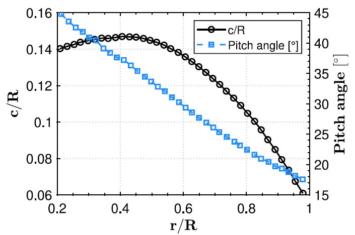
The experimental setup consisted of two propulsion units with two-bladed propellers mounted on a wing, representing a distributed electric propulsion (DEP) configuration. Each propeller had a diameter(D) of 9 in. (228.6 mm), a pitch-to-diameter ratio of P/D = 1, and was made of carbon fiber/epoxy materials with a Clark-Y aerofoil section. The blades were constant-pitch with both pitch and diameter set to 9 in.(228.6 mm), and their chord and pitch angle distributions are shown in Figure 1. The wing featured a NACA0018 profile, with a chord length (c) of 0.3 m, a span (L) of 0.94 m, and was constructed from 6000 series aluminum. The propellers were installed with a spacing of 150 mm between the trailing edge of the propeller and the leading edge of the wing. The combined propeller–wing assembly was mounted in an open-jet wind tunnel, positioned such that the propeller was located approximately 0.5 m downstream of the nozzle exit, and normal in relation to the tunnel free-stream flow. Based on prior findings [7], both propellers were set to rotate co-directionally, in a counterclockwise direction when viewed from the front, as this configuration enhances synchronization benefits compared to counter-rotating arrangements.
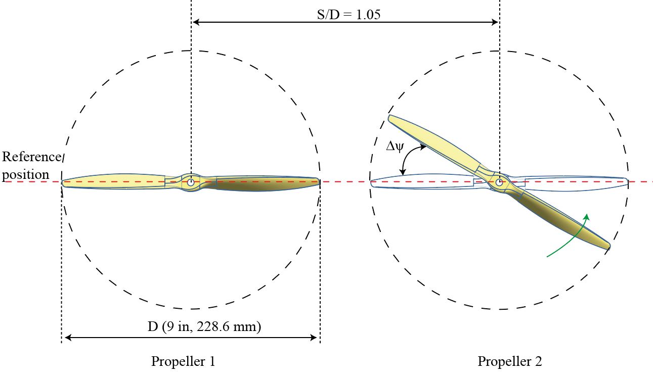
The geometric definition of Δψ and the setup layout are illustrated in Figure 2, with the center-to-center propeller spacing fixed at s/D = 1.05 to limit aerodynamic coupling and isolate acoustic interference effects. Propeller 1 acted as the master, while Propeller 2 was the slave, with blade adjustments on Propeller 2 generating seven relative phase angles. These ranged from Δψ = 0° to 90°, in 15° increments, enabling systematic investigation of noise attenuation effects.
Measurement Location and Techniques
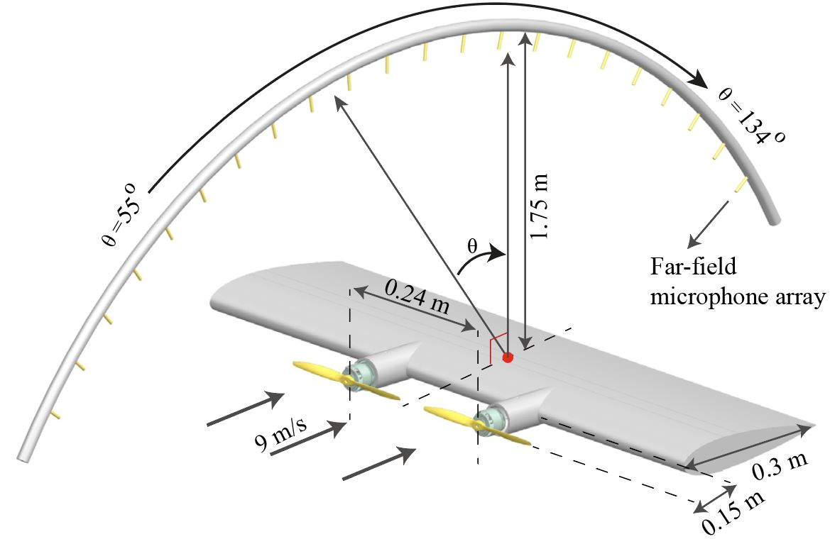
To capture far-field noise characteristics, an overhead array of 18 microphones was deployed, covering angles from 55° to 134°, as shown in Figure 3. The array was centered at the 90° position, located 1.75 m above the center of the wing and equidistant between the two propellers. This arrangement ensured accurate spatial coverage of the acoustic field generated during testing.
Noise data were recorded using 1/4-inch G.R.A.S 40PL free-field microphones, operating across a frequency range of 10 Hz to 20 kHz with a dynamic range of 142 dB and ±1 dB accuracy. Signals were sampled at 216 Hz for 40 seconds using a National Instruments PXIe-4499 Sound and Vibration module. Power spectra were calculated with the MATLAB Pwelch method, yielding results with a frequency resolution of 1 Hz. The Sound Pressure Level (SPL) from each microphones and the OverAll Sound Pressure Level (OASPL) from all the microphones are presented in the dataset.
Experimental Facility
The experiments were conducted in the aeroacoustic wind tunnel at the University of Bristol. This facility is a temperature-controlled, closed-circuit, open-jet wind tunnel designed for aeroacoustic testing. It provides a free-stream velocity range between 4 m/s and 40 m/s, with turbulence intensity as low as 0.2% in an anechoic environment.
The wind tunnel features a nozzle with a width of 0.5 m and a height of 0.775 m, operating with a contraction ratio of 8.4. The test chamber is acoustically treated, offering an approximate cut-off frequency of 160 Hz in compliance with ISO 3745 standards. To minimize acoustic reflections, all exposed surfaces, including the model support struts, anechoic chamber walls, and contraction nozzle are covered with foam wedges.
Flow Conditions
Inlet velocity = 0, 9, 10, 12, and 14 m/s.
Free-stream turbulence ≈\approx 0.2 %.
Propeller rotational speed = 5000 rpm.
Advance ratio(J) = 0, 0.47, 0.53, 0.63 and 0.73.
Blade Passing frequency of two bladed propeller = 166.6 Hz.
Total number of microphones = 25.
CAD files
The CAD geometry of the propeller can be downloaded from here
Available Datasets
| Baseline (0 m/s), J = 0 | ||
|---|---|---|
| Phase angle (degree) |
SPL | OASPL (100 Hz < ƒ < 1000 Hz) |
| 0° | J_0_phase_0_SPL.csv | J_0_phase_0_OASPL.csv |
| 15° | J_0_phase_15_SPL.csv | J_0_phase_15_OASPL.csv |
| 30° | J_0_phase_30_SPL.csv | J_0_phase_30_OASPL.csv |
| 45° | J_0_phase_45_SPL.csv | J_0_phase_45_OASPL.csv |
| 60° | J_0_phase_60_SPL.csv | J_0_phase_60_OASPL.csv |
| 75° | J_0_phase_75_SPL.csv | J_0_phase_75_OASPL.csv |
| 90° | J_0_phase_90_SPL.csv | J_0_phase_90_OASPL.csv |
| 9 m/s, J = 0.47 | ||
|---|---|---|
| Phase angle (degree) |
SPL | OASPL (100 Hz < ƒ < 1000 Hz) |
| 0° | J_0.47_phase_0_SPL.csv | J_0.47_phase_0_OASPL.csv |
| 15° | J_0.47_phase_15_SPL.csv | J_0.47_phase_15_OASPL.csv |
| 30° | J_0.47_phase_30_SPL.csv | J_0.47_phase_30_OASPL.csv |
| 45° | J_0.47_phase_45_SPL.csv | J_0.47_phase_45_OASPL.csv |
| 60° | J_0.47_phase_60_SPL.csv | J_0.47_phase_60_OASPL.csv |
| 75° | J_0.47_phase_75_SPL.csv | J_0.47_phase_75_OASPL.csv |
| 90° | J_0.47_phase_90_SPL.csv | J_0.47_phase_90_OASPL.csv |
| 10 m/s, J = 0.53 | ||
|---|---|---|
| Phase angle (degree) |
SPL | OASPL (100 Hz < ƒ < 1000 Hz) |
| 0° | J_0.53_phase_0_SPL.csv | J_0.53_phase_0_OASPL.csv |
| 15° | J_0.53_phase_15_SPL.csv | J_0.53_phase_15_OASPL.csv |
| 30° | J_0.53_phase_30_SPL.csv | J_0.53_phase_30_OASPL.csv |
| 45° | J_0.53_phase_45_SPL.csv | J_0.53_phase_45_OASPL.csv |
| 60° | J_0.53_phase_60_SPL.csv | J_0.53_phase_60_OASPL.csv |
| 75° | J_0.53_phase_75_SPL.csv | J_0.53_phase_75_OASPL.csv |
| 90° | J_0.53_phase_90_SPL.csv | J_0.53_phase_90_OASPL.csv |
| 12 m/s, J = 0.63 | ||
|---|---|---|
| Phase angle (degree) |
SPL | OASPL (100 Hz < ƒ < 1000 Hz) |
| 0° | J_0.63_phase_0_SPL.csv | J_0.63_phase_0_OASPL.csv |
| 15° | J_0.63_phase_15_SPL.csv | J_0.63_phase_15_OASPL.csv |
| 30° | J_0.63_phase_30_SPL.csv | J_0.63_phase_30_OASPL.csv |
| 45° | J_0.63_phase_45_SPL.csv | J_0.63_phase_45_OASPL.csv |
| 60° | J_0.63_phase_60_SPL.csv | J_0.63_phase_60_OASPL.csv |
| 75° | J_0.63_phase_75_SPL.csv | J_0.63_phase_75_OASPL.csv |
| 90° | J_0.63_phase_90_SPL.csv | J_0.63_phase_90_OASPL.csv |
| 14 m/s, J = 0.73 | ||
|---|---|---|
| Phase angle (degree) |
SPL | OASPL (100 Hz < ƒ < 1000 Hz) |
| 0° | J_0.73_phase_0_SPL.csv | J_0.73_phase_0_OASPL.csv |
| 15° | J_0.73_phase_15_SPL.csv | J_0.73_phase_15_OASPL.csv |
| 30° | J_0.73_phase_30_SPL.csv | J_0.73_phase_30_OASPL.csv |
| 45° | J_0.73_phase_45_SPL.csv | J_0.73_phase_45_OASPL.csv |
| 60° | J_0.73_phase_60_SPL.csv | J_0.73_phase_60_OASPL.csv |
| 75° | J_0.73_phase_75_SPL.csv | J_0.73_phase_75_OASPL.csv |
| 90° | J_0.73_phase_90_SPL.csv | J_0.73_phase_90_OASPL.csv |
Sample plots
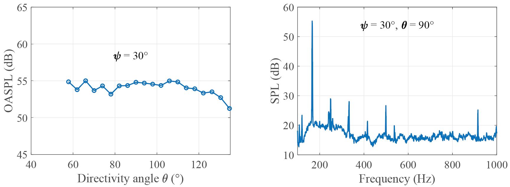
To help you analyze the dataset, a MATLAB script has been provided. This script can be used to automatically create plots of SPL and OASPL, and the sample plots using the matlab code is given in figure 4.
Open Access
This metadata is provided under the Creative Commons Attribution-NonCommercial 4.0 International License https://creativecommons.org/licenses/by-nc/4.0/). This license allows for unrestricted use, distribution, and reproduction in any medium, provided that proper credit is given to the original author(s) and the source. Also provide a link to the license, and indicate if any changes were made. Furthermore, this license does not allow the use of this material for commercial purposes.
Acknowledgments
The NWTF acknowledge the support for the metadata work from the EPSRC Network Grant, EP/X011836/1. The original dataset was funded by the European Union’s Horizon 2020 Research and Innovation Programme under Grant Agreement No. 882842 (SilentProp project).
Citation
If the user wants to cite the data presented here, then please cite both the NWTF metadata and the corresponding paper[6].
References
- Baledon, M.S. and Kosoy, N., 2018. “Problematizing” carbon emissions from international aviation and the role of alternative jet fuels in meeting ICAO’s mid-century aspirational goals. Journal of Air Transport Management, 71, pp.130-137.DOI
- Rizzi, S.A., Huff, D.L., Boyd, D.D., Bent, P., Henderson, B.S., Pascioni, K.A., Sargent, D.C., Josephson, D.L., Marsan, M., He, H.B. and Snider, R., 2020. Urban air mobility noise: Current practice, gaps, and recommendations (No. NASA/TP-20205007433).Web link
- Kim, H.D., Perry, A.T. and Ansell, P.J., 2018, July. A review of distributed electric propulsion concepts for air vehicle technology. In 2018 AIAA/IEEE Electric Aircraft Technologies Symposium (EATS) (pp. 1-21). IEEE.DOI
- Turhan, B., Jawahar, H.K., Bowen, L., Rezgui, D. and Azarpeyvand, M., 2023, July. Aeroacoustic characteristics of single propeller-wing configuration. In International Institute of Acoustics and Vibration, The 29th International Congress on Sound and Vibration.Web link
- Lee, H. and Lee, D.J., 2020. Rotor interactional effects on aerodynamic and noise characteristics of a small multirotor unmanned aerial vehicle. Physics of Fluids, 32(4).DOI
- Turhan, B., Jawahar, H.K., Gautam, A., Syed, S., Vakil, G., Rezgui, D. and Azarpeyvand, M., 2024. Acoustic characteristics of phase-synchronized adjacent propellers. The Journal of the Acoustical Society of America, 155(5), pp.3242-3253.DOI
- Shao, M., Lu, Y., Xu, X., Guan, S. and Lu, J., 2022. Experimental study on noise reduction of multi-rotor by phase synchronization. Journal of Sound and Vibration, 539, p.117199.DOI