
Aerodynamics and Aeroacoustics of Stationary and Pitching NACA 0012 and NACA 16-506 Aerofoils
 ✉
Esmaeel Massoudi ✉
Mahdi Azarpeyvand ✉
Affiliation : School of Civil, Aerospace and Design Engineering, University of Bristol, Queens Building, University Walk, Bristol, BS8 1TR
✉ mh17262@bristol.ac.uk; ✉ e.masoudi@bristol.ac.uk; ✉ m.azarpeyvand@bristol.ac.uk
Introduction:
Aerodynamic noise from wind turbines, aircraft, propellers, and other aerodynamic systems is an important source of environmental noise. For aerofoils operating under steady conditions, the principal self-noise mechanisms are comparatively well established, including turbulent-boundary-layer trailing-edge noise, laminar-boundary-layer vortex-shedding noise, separation and stall noise, trailing-edge bluntness noise, and tip-vortex noise [1]. Among these, stall noise is associated with large-scale flow separation and increased surface-pressure fluctuations. In many practical applications, however, aerofoils operate under continuously changing conditions. A familiar example is a helicopter rotor blade, which can experience substantial variations in angle of attack as it rotates. Under such rapidly varying inflow or pitching conditions, the aerodynamic response becomes unsteady and the mechanisms governing stall and its associated noise become considerably more complex.
Under these conditions, the instantaneous flow response can differ from that observed at the same angle of attack under stationary conditions. Separation may be delayed beyond the static stall angle, producing aerodynamic hysteresis and large variations in lift and pitching moment [2,3]. Depending on the motion, the aerofoil may undergo light or deep dynamic stall. In deep dynamic stall, the leading-edge shear layer rolls up into a coherent dynamic stall vortex, which grows and convects over the aerofoil before lifting away from the surface. The resulting vortex evolution, large-scale separation and delayed reattachment generate strongly phase-dependent aerodynamic loads and pressure fluctuations. Despite extensive research into the aerodynamics of dynamic stall, the associated aeroacoustic mechanisms remain comparatively less understood.
This dataset provides complementary stationary and pitching measurements for NACA 0012 and NACA 16-506 aerofoils, including aerodynamic loads, surface-pressure distributions, and near-field and far-field pressure measurements. The data enable investigation of stall development and dynamic-stall noise mechanisms, provide benchmark measurements for computational and analytical model validation, and support the development of noise-mitigation strategies for unsteady aerodynamic systems.
Model geometry
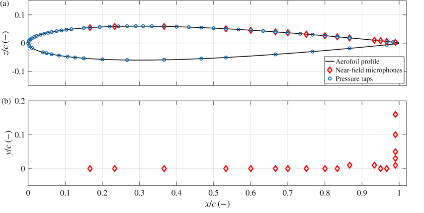
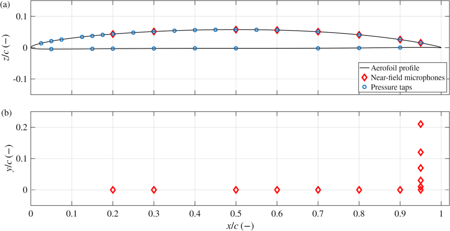
The experiments were conducted using NACA 0012 and NACA 16-506 aerofoils, both with a chord length of c = 300 mm and a span of 500 mm within the test section. The profiles are defined using nondimensional coordinates, x/c and y/c, with the coordinate origin located at the leading edge and mid-chord. Both aerofoils were tripped at x/c = 0.1 using a 6 mm wide and 0.5 mm thick zig-zag 3D turbulator trip tape supplied by Glasfaser-Flugzeug-Service GmbH on both the suction and pressure surface. The aerofoil models were mounted to pitch about the quarter-chord axis, with the dynamic motion generated using a servo-motor system positioned outside the Kevlar test section. Similar experimental setups and further inside on a different airfoil can be seen in Masoudi, Zang and Azarpeyvand [4], and Mayer, Zang and Azarpeyvand [5]. The NACA 0012 aerofoil profile and instrumentation layout are shown in Figure 1, including the locations of the surface-pressure taps and near-field microphones. The corresponding aerofoil coordinates and instrumentation locations are provided in a single .csv file, NACA0012_coordinates. The NACA 16-506 aerofoil profile and instrumentation layout are shown in Figure 2, including the corresponding surface-pressure tap and near-field microphone locations. The aerofoil coordinates and instrumentation locations are likewise provided in a single .csv file, NACA16506_coordinates.
Measurement Locations and Techniques
The experiments combined aerodynamic, surface-pressure and acoustic measurements for stationary and sinusoidally pitching aerofoils. The instantaneous aerofoil angle was independently measured using a laser displacement sensor to accurately capture the airfoil’s motion. Steady surface-pressure measurements were obtained using pressure taps distributed over the suction and pressure surfaces of the aerofoil. These measurements were used to determine chordwise pressure-coefficient distributions and the corresponding aerodynamic lift and pitching-moment coefficients.
Unsteady pressure measurements were acquired using near-field microphones positioned beneath small surface pinholes distributed along the aerofoil chord. For the NACA 0012 aerofoil, the chordwise microphones were installed directly beneath the surface pinholes, while the microphones located near the trailing edge employed a remote-sensing arrangement [5,7,8]. In contrast, all microphones used for the NACA165-506 aerofoil employed remote sensing. These measurements were processed to obtain the surface-pressure power spectral densities (PSDs) and signal energy content (SEC) quantities.
The SEC is defined as:
where represents the surface-pressure power spectral density.
For the NACA 0012 dataset, the SEC is integrated over f1=160Hz and f2=10kHz. For the NACA 16-series dataset, f2 is restricted to 5 kHz. This reduced frequency range reflects the bandwidth limitation associated with the remote-sensing surface-pressure measurement used for the NACA 16-series experiments, for which reliable surface-pressure data are available only up to approximately 5 kHz. The SEC therefore provides a nondimensional measure of the integrated surface-pressure fluctuation energy over the usable frequency range of each dataset.
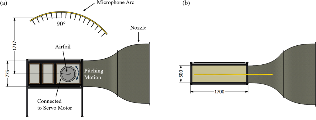
Far-field acoustic measurements were obtained using an overhead microphone array positioned above the aerofoil. The published dataset includes the microphone located at 90°, positioned vertically above the aerofoil as shown in Figure 3(a). This microphone was located 1.717 m from the aerofoil trailing edge when the aerofoil is at = 0.
Experimental Facility
The experiments were conducted in the University of Bristol aeroacoustic wind tunnel, a temperature-controlled, closed-circuit facility with an open-jet test section designed for aerodynamic and aeroacoustic measurements [6]. The tunnel operates over a free-stream velocity range of 4–40 m/s and can achieve turbulence intensities as low as 0.2%. The contraction nozzle has an exit width of 0.50 m and a height of 0.775 m. The aeroacoustic test chamber measures 7.9 m × 5.0 m × 4.6 m and is acoustically treated, providing effectively anechoic conditions above 160 Hz. The experimental arrangement is illustrated in Figure 3, which shows annotated front and top views of the setup. The aerofoil model was installed within a Kevlar-walled test section. The Kevlar walls minimise disturbance to the aerodynamic flow while allowing acoustic radiation to propagate through the test-section boundaries for far-field measurements. Exposed surfaces within the chamber and the model-support structures were acoustically treated to minimise unwanted reflections. Corrections for acoustic attenuation associated with the Kevlar walls and the test-section boundary layers have been reported by Devenport et al [7]. These corrections have not been applied to the far-field data provided in this dataset. Keen readers can follow the method outlined in Mayer[8].
Aerofoil Coordinates and Pressure Tap Locations
NACA0012_coordinates.
NACA16506_coordinates.
Flow Conditions
- Freestream velocity: m/s
- Chord-based Reynolds number:
- Stationary angles of attack: –
- Sampling frequency: Hz
- Measurement duration per case:
- Stationary cases: 32 s
- Dynamic cases: Time to complete 50 cycles
- Reduced frequency:
- Dynamic test cases
NACA0012
| Mean angle, α₀ | Pitching amplitudes, A | k = 0.02 | k = 0.05 | k = 0.1 |
|---|---|---|---|---|
| 5° | 4° | ✓ | ✓ | ✓ |
| 10° | 4°, 8°, 12° | ✓ | ✓ | ✓ |
| 12° | 4°, 8°, 12° | ✓ | ✓ | ✓ |
| 15° | 4°, 8°, 12° | ✓ | ✓ | ✓ |
NACA16506
| Mean angle, α₀ | Pitching amplitudes, A | k = 0.02 | k = 0.05 | k = 0.1 |
|---|---|---|---|---|
| 5° | 4° | ✓ | ✓ | ✓ |
| 10° | 4°, 8°, 12° | ✓ | ✓ | ✓ |
| 12° | 4°, 8°, 12° | ✓ | ✓ | ✓ |
| 15° | 4°, 8° | ✓ | ✓ | ✓ |
| 15° | 12° | ✓ | ✓ | — |
The airfoil starts at the minimum angle of attack at , pitches up to the maximum angle at , and returns to the minimum angle at , completing one sinusoidal pitching cycle.
Available Datasets
(i) Stationary test cases – NACA0012
(ii) Dynamic Test Cases – NACA0012
(iii) Stationary test cases – NACA16506
(iv) Dynamic Test Cases – NACA16506
Code and Sample plots
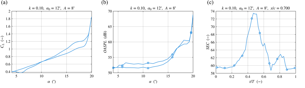
A MATLAB script plot_NWTF_CSV.mat is provided to demonstrate how to access, process and visualise the submitted dataset. Example outputs generated using the supplied scripts are shown in Figure 4.
Complete Dataset
The complete dataset is available for download here. It contains the full experimental datasets for both the NACA 0012 and NACA 16-506 aerofoils, together with a user guide for each dataset explaining the file structure and how to access the stored variables. The datasets include both stationary and dynamically pitching conditions and contain the processed aerodynamic and aeroacoustic measurements used in the study. Raw files have not been stored in the h5 file; however, it is a more compact way of storing and downloading the entire dataset.
Open Access
This metadata is provided under the Creative Commons Attribution-NonCommercial 4.0 International License https://creativecommons.org/licenses/by-nc/4.0/). This license allows for unrestricted use, distribution, and reproduction in any medium, provided that proper credit is given to the original author(s) and the source. Furthermore, this license does not allow the use of this material for commercial purposes.
Acknowledgements
The authors express their gratitude for the support from the Engineering and Physical Sciences Research Council (EPSRC) of the United Kingdom under Grant No. EP/X019284/1, titled Aeroacoustics of Dynamic Stall
References
- Brooks, T.F., Pope, D.S. and Marcolini, M.A. (1989) Airfoil self-noise and prediction. NASA Reference Publication 1218. Hampton, VA: NASA Langley Research Center.
- McCroskey, W.J. (1981) The phenomenon of dynamic stall. NASA Technical Memorandum 81264. Moffett Field, CA: NASA Ames Research Center.
- Hadjipantelis, M., Masoudi, E., Zang, B. and Azarpeyvand, M. (2026) ‘Aerodynamics and aeroacoustics of dynamic stall of a pitching NACA 65-410 airfoil’, in 32nd AIAA/CEAS Aeroacoustics Conference. American Institute of Aeronautics and Astronautics. doi: 10.2514/6.2026-3469.DOI
- Masoudi, E., Zang, B., Azarpeyvand, M. (2026) ‘Experimental study of the aeroacoustic behavior of a pitching NACA65-410 airfoil’, Journal of Sound and Vibration, 621, 119494. DOI
- Mayer, Y.D., Zang, B., Azarpeyvand, M. (2020) ‘Aeroacoustic investigation of an oscillating airfoil in the pre- and post-stall regime’, Aerospace Science and Technology, 103, 105880. DOI
- Mayer, Y.D., Jawahar, H.K., Szőke, M., Ali, S.A.S., Azarpeyvand, M. (2019) ‘Design and performance of an aeroacoustic wind tunnel facility at the University of Bristol’, Applied Acoustics, 155, pp.358-370. DOI
- Devenport, W.J., Burdisso, R.A., Borgoltz, A., Ravetta, P.A., Barone, M.F., Brown, K.A. and Morton, M.A. (2013) ‘The Kevlar-walled anechoic wind tunnel’, Journal of Sound and Vibration, 332(17), pp. 3971–3991. DOI
- Mayer, Y.D. (2020). Aeroacoustic Characteristics of Static and Dynamic Stall. University of Bristol. PhD Thesis


